POE CALCULATOR
CALCULATION OF POE CHARACTERISTICS

- Power required by the end application (watt)
- PSE output voltage. Typical value Vpse=54...57V
- Select the type of the cable
- The length of the cable (maximum value L=100m)
- Selected system configuration (2-pair or 4-pair)
- Expected PD efficiency in decimal. It should take into account losses in the rectifiers, PD controller and DC-DC converter. Typical value η=0.85...0.93
Note that if the calculated power required from PSE is >100W, you won't be able to find a compliant PSE for such an application. In this case, you may try using a shorter cable, increasing Vpse, and/or increasing PD efficiency. Alternatively, you may consider using two ports with current sharing (power combining).
POE SYSTEM POWER EQUATIONS
For a reference, the power equations for PoE systems are the following.
Power that needs to be available at the input of PD: P=W/η,
where W- wattage required for your end application, η- efficiency of PD in decimal.
Voltage at the PD input:
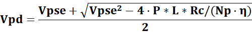 where Vpse- voltage at PSE output, L- length of the cable (meters), Rc=0.125 Ω/meter - loop resistance of each pairset (which is total resistance of forward and return pairs in each pairset), Np- number of pairsets (Np=1 for 2-pair systems, Np=2 for 4 pair-system).
Net current in the cable: Icable=P/Vpd;
Current in each pairset: Ip=Icable/Np;
Required minimum power of PSE: Ppse=Vpse*Icable
Losses in the cable: Pcable=Icable2*Rc*L/Np
ASSUMPTIONS:
1. In our calculations we neglected a possible imbalance between pairs, so for 4-pair system we assumed Icable=2*Ip (for 2-pair system by definition Icable=Ip). In practice, there is always certain imbalance, although very small because impedances of individual pairs in the same cable are pretty much identical.
2. We used the following DC resistances Rc of each loop: CAT5/e: 0.125 Ω/meter; CAT6/e: 0.09 Ω/meter; CAT3: 0.2 Ω/meter. These values represent typical maximum DC resistances at 100 OC.
If you want the above App on your Android phone, get it here.